Basic Disassembly of the Baofeng UV-5R
- 7 minsSummary:
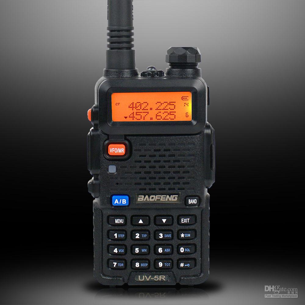
Prolific within the intersection between amateur radio and civilian tactical groups, the Baofeng UV-5R is an exceptional first choice for anyone trying to understand programmable radios and their application within the field. I rarely use mine, if at all, so I figured it’s better suited in the queue for teardown. A preliminary glance at programming / operation of the radio can be found here [0]. This post is less about the disassembly and more about the “having the option to do it”, the basic idea behind identifying integrated components on a board, and lifting binaries from EEPROMs.
Overview
Disassembly
I don’t take credit for the disassembly video [1]; it was particularly useful for tearing down the coax port / feed line. Prior to removing the UV-5R’s face, various header components had to be removed or at least loosened in order for me to have access to the board. I resorted to using an iFixit Precision Toolkit which was more than enough for my purposes. I recommend following this video to the ‘T’ if you intend on reassembling the radio; my method was clumsy at best, so a couple of components (namely the coax and LED) were slightly bent, but not horrifically so. Also, if anyone asks, I’m using a generic mouse pad as my “workspace” as opposed to an ESD mat on a lab bench. I’m not overly concerned with breaking this radio, and it’s relatively inexpensive, so I did not take those precautions. Anyway, successful disassembly roughly results in:
- a backplate with spongy contact pads
- a rubber button cutout
- a display panel (which is situated against the plastic face cover for data display)
- at least 16 screws (four various sizes, depending on mounting point)
- a volume dial
- butt plate (also plastic in composition)
- a speaker which is glued to the front face of the radio
- a wire which is soldered between the speaker and contact patches on the circuit board
- of course, the circuit board itself.
A lot of this is stuff you can find on forums across the internet, ranging from RU to JP.
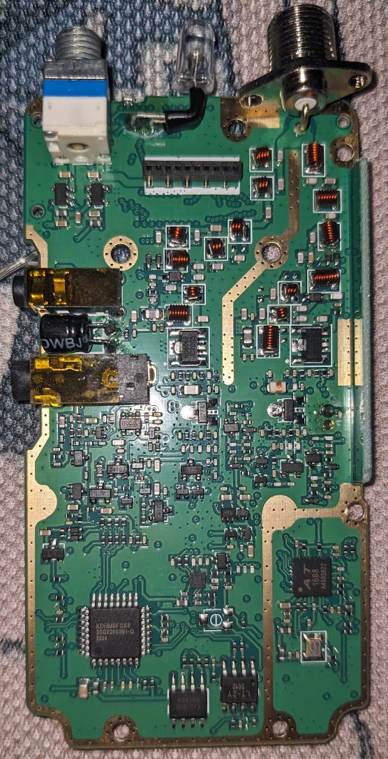
Components
Really helpful resource for identifying integrated component datasheets [2]. A lot of the circuitry was identified here [3], to include components of interest. It’s worth noting the differences between the models, but the overall function of the radio should not change. The most interesting ones I identified (of the ones I could actually discern):
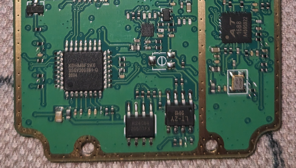
- KDHM8F2K6 8-Bit Microcontroller, Serial No. 3SGV200391-Q 2034
- Still unsure of what kind of microcontroller this is, but it’s the brain of the unit. Some affordable 8-bit RISC processor would be my guess.
- K24C64 EEPROM, Serial No. 2050TFX
- Two-wire serial EEPROM (electrically erasable programmable read-only memory).
- I2C EEPROM supports a maximum clock frequency of 400 KHz. Data is organized in eight 8192 bit blocks [4].
- AT1688, Serial No. A459S922
- No direct references, but given placement on board (proximal to push-to-talk button), might be a transceiver chip.
- In separate reference, found this: чип трансивера на три диапазона, но увы диапазоны 200-260 МГц не добавлены в рацию
- Translates to … Transceiver chip for three bands, excluding 200-260 MHz.
- LT-ZY2012, Serial No. 2012; unidentified.
- TDA2822A, Serial No. ZXAX050
- Monolithic integrated audio amplifier in an 8-pin plastic dual in-line package, designed for portable cassette players and radios [5].
Lifting Firmware
We’ve identified our EEPROM component, so we leverage our data sheet to identify form factor and pinout configuration. Looks something like this:
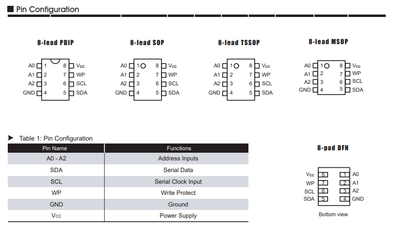
Let’s scrutinize our EEPROM some more to figure out where pin 1 is: 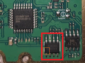
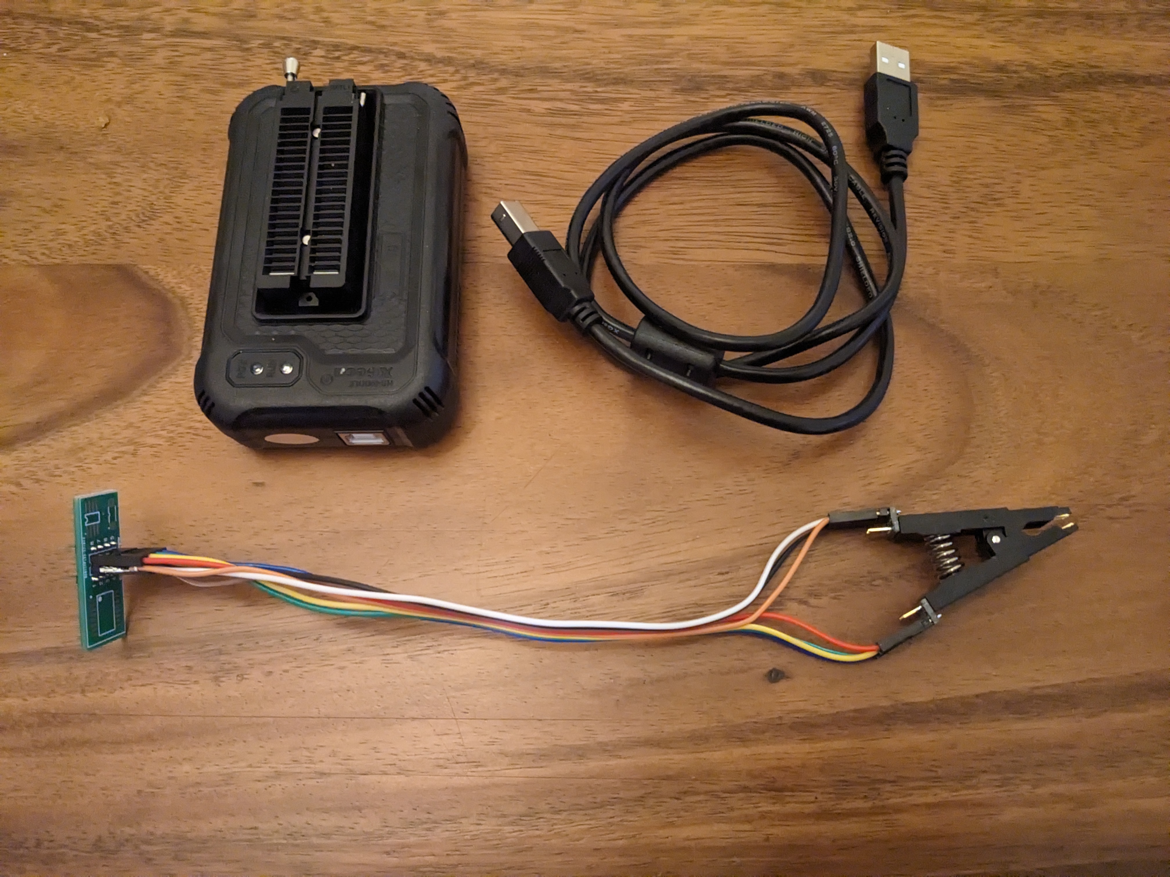
Now we formulate some kind of plan for lifting the firmware itself. Fortunately we have all the equipment we need. If we didn’t, we might consider something like this:
- XGecu Pro T48 Programmer.
- Multimeter tips / testing kit.
- EEPROM adapters for the T48 programmer.
- If we chose to use a lab bench power supply, we’d consider using plungers, wires, and leads.
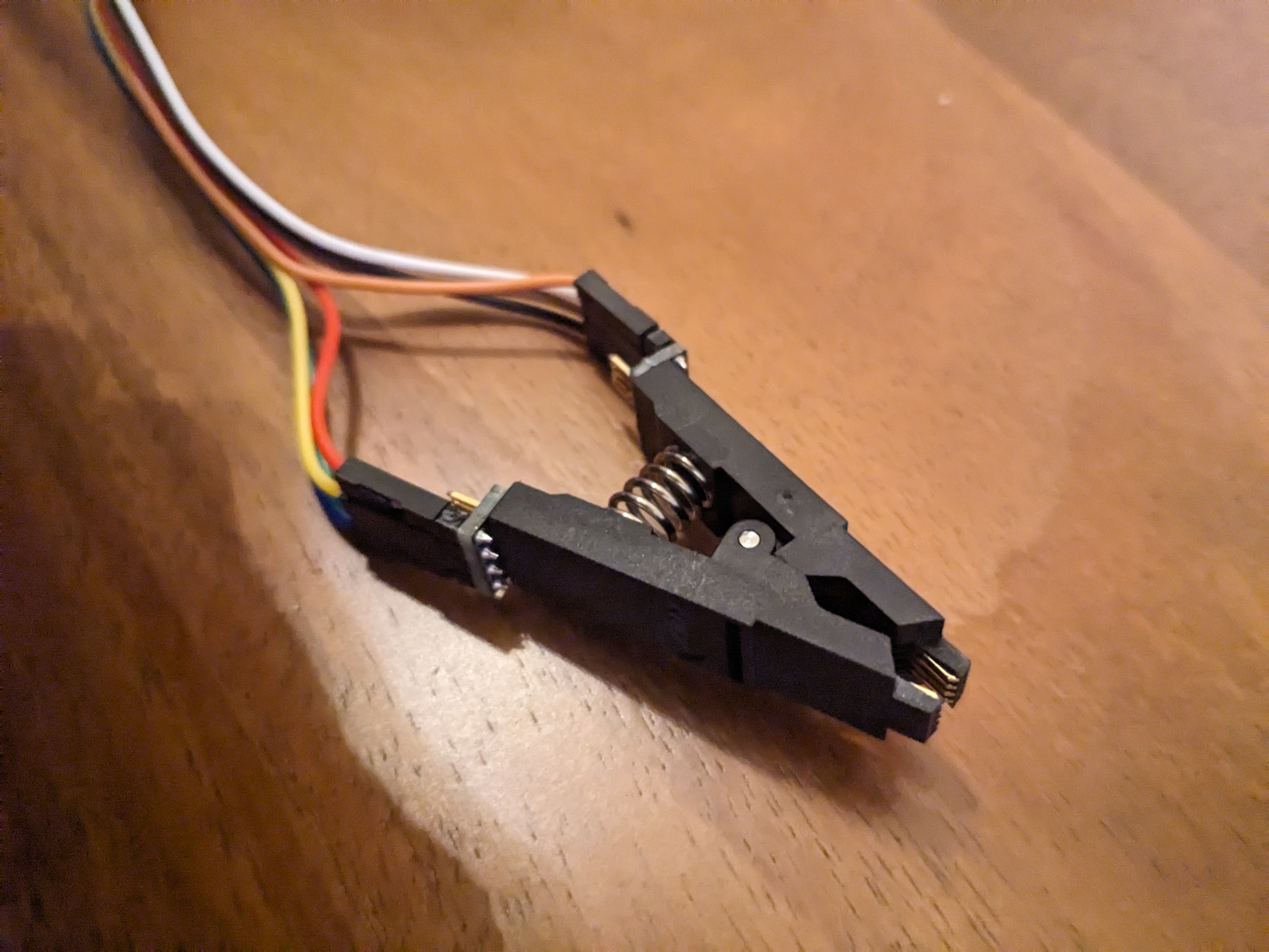
- The 8-pin SOIC test clips are roughly analogous to alligator clips that attach nicely to the 8-pin EEPROM on the board.
- The pins at the top of the 8-pin testing clip give pin-by-pin access which we could wire up however we’d like.
- Possibly need electrical tape for binding the “pin extensions” onto the leads (for example, for serial interface or Vcc / GND from the bench power supply).
- We might consider this option if we didn’t have EEPROM adapters, and if we only had pins and datasheets to go off of.
Thankfully the T48 simplifies all of this… Quick overview of the hardware, featuring the T48 Programmer, SOIC adapter, wires for the pin-out configuration, and the clip which attaches to the EEPROM on the board:
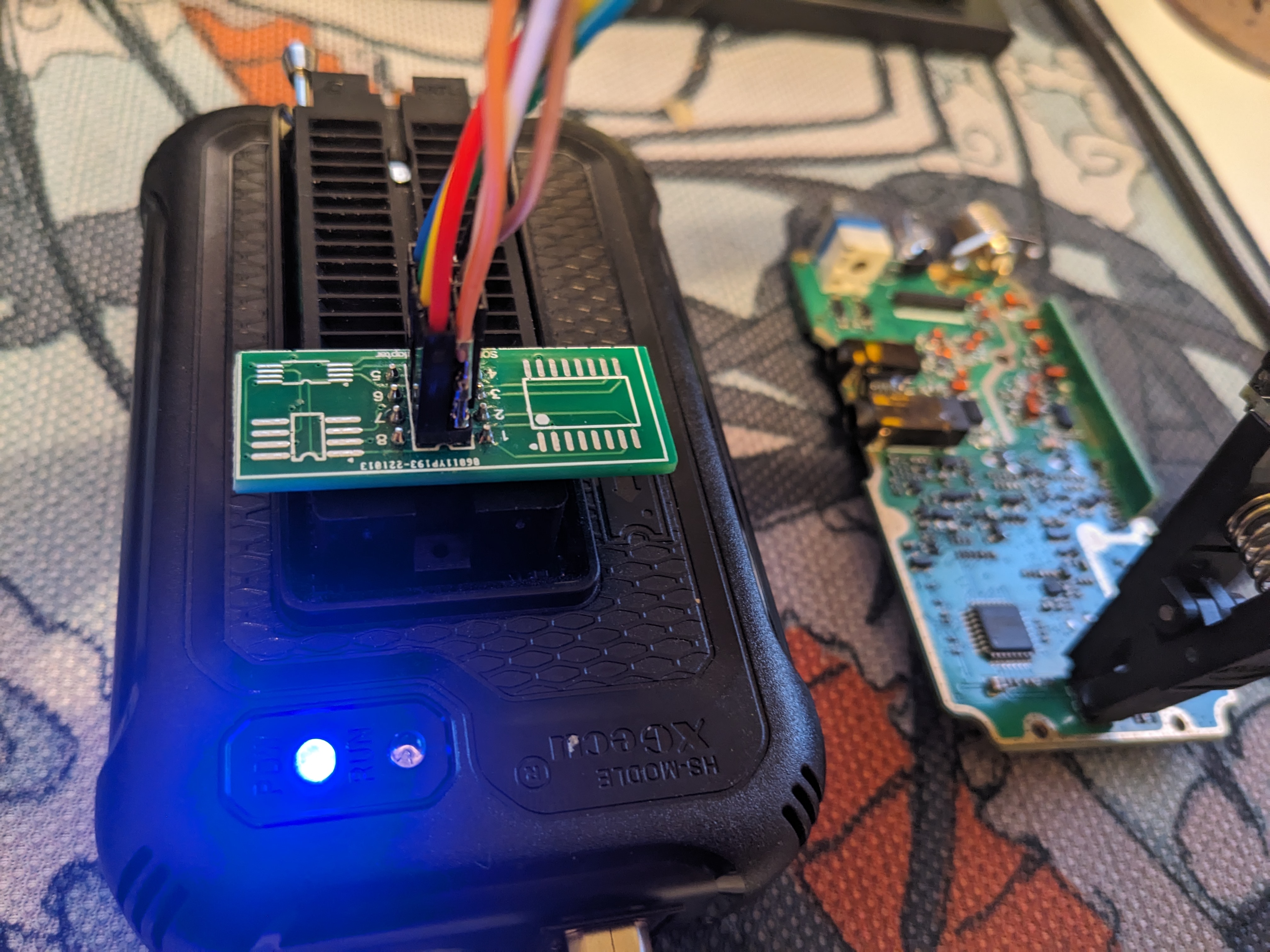
The T48 Programmer interfaces with a host / virtual machine over USB 2.0, Type B; configuration looks something like this with the wires matching up between the SOIC adapter pin-out and the EEPROM on the board itself. I used the reference above to guide wire placement.
I stood up a Windows 10 virtual machine to run the Xgecu-provided software, named “Xgpro” (Version 12.63) [6]. Necessitated installing something to unpack the .RAR archive (7z for the win). There is at least one part of the installation process that requires elevated permissions; it installs a USB driver for the T48 programmer. Pro tip: if you want to simplify the setup of a Windows 10/11 machine in VMWare, you can remove the virtualized network interface during installation and setup from the Windows media image. This bypasses a lot of the bloat of standing up accounts with Microsoft, all of that. Anyway, downloading and installing is simple.
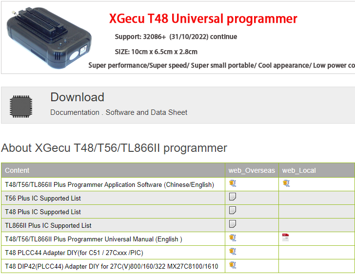
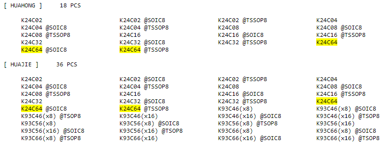
While we’re at it, we can review the online documentation provided by Xgecu to verify that the IC in question is supported by the T48 Programmer (specifically the K24C64 chip). We see a variety of form factors and models here…
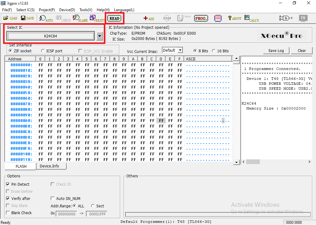
Post installation inside of our WIN10 virtual machine, we’re presented with the Xgpro software interface. The graphical interface looks something like this. We’re primarily concerned with two aspects: the read function and the IC we’ll be reading from. We also have the option - after reading the contents of the chip - to dump the binary into a file of our choice, from the File tab.
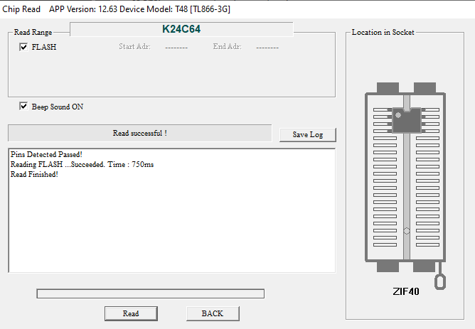
Quick verification of our setup, hit the Read button, and the T48 works the magic for us. By default, T48 Programmer will run an initial debugging sequence to ensure that the pin configuration is correct. It does a pretty great job of telling you something is wrong, and provides visuals to help orient yourself if, for example, you misplaced the adapter. The results follow. Again, we could save this off into a separate binary file if we wanted to. The hex dump will be presented in the main window on the Xgecu interface.
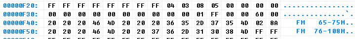
A quick review of the binary contents leads me to believe that this is the storage location of a “.IMG” that may be generated by radio programming software. Chirp is a popular choice. The remainder of the binary blob is composed of “0xFF” binary content with a few things here and there, such as the firmware “HELLO” message, a potential “preamble”, and a BaoFeng firmware version identifer .

References
[0] https://wiki.radioreference.com/index.php/Baofeng_UV-5R
[1] https://www.youtube.com/watch?v=uvRocFQHOy0
[2] https://www.alldatasheet.com/
[3] https://www.allaboutcircuits.com/news/teardown-tuesday-baofeng-amateur-radio-transceiver/
[4] https://datasheet.lcsc.com/lcsc/1808091831_Hua-Hong-NEC-K24C32_C173181.pdf
[5] https://www.digchip.com/datasheets/parts/datasheet/670/TDA2822A-pdf.php
[6] http://www.xgecu.com/EN/index.html
[7] https://chirp.danplanet.com/projects/chirp/wiki/Home